As the description says, there is a project where I basically want to have an impact wrench connect to a computer. In the long term, I would actually like to design my own impact wrench because they are super cool, but I think in the short term, I want to validate this small project idea.
As a result, I bought this impact wrench, which it says should be able to provide 400 Nm. That is a lot and would be super cool.
That being said, since I am stripping out the trigger and basic electronics, I will need to figure out a substitute "trigger" control mechanism as well as a mount for the actual actuation.
Last week, I was in MITERs trying to figure out if I would be able to power this separately.
This is my second time tearing apart something and really trying to figure out what its PCB does. The first time was at a Bad Bunny concert in the Dominican Republic where they gave out these necklaces with flashing lights.


I need to go back and actually figure out more, but with the help of Elijah in MITERS and looking confused for a small amount of time, I was generally able to figure out what is going on.
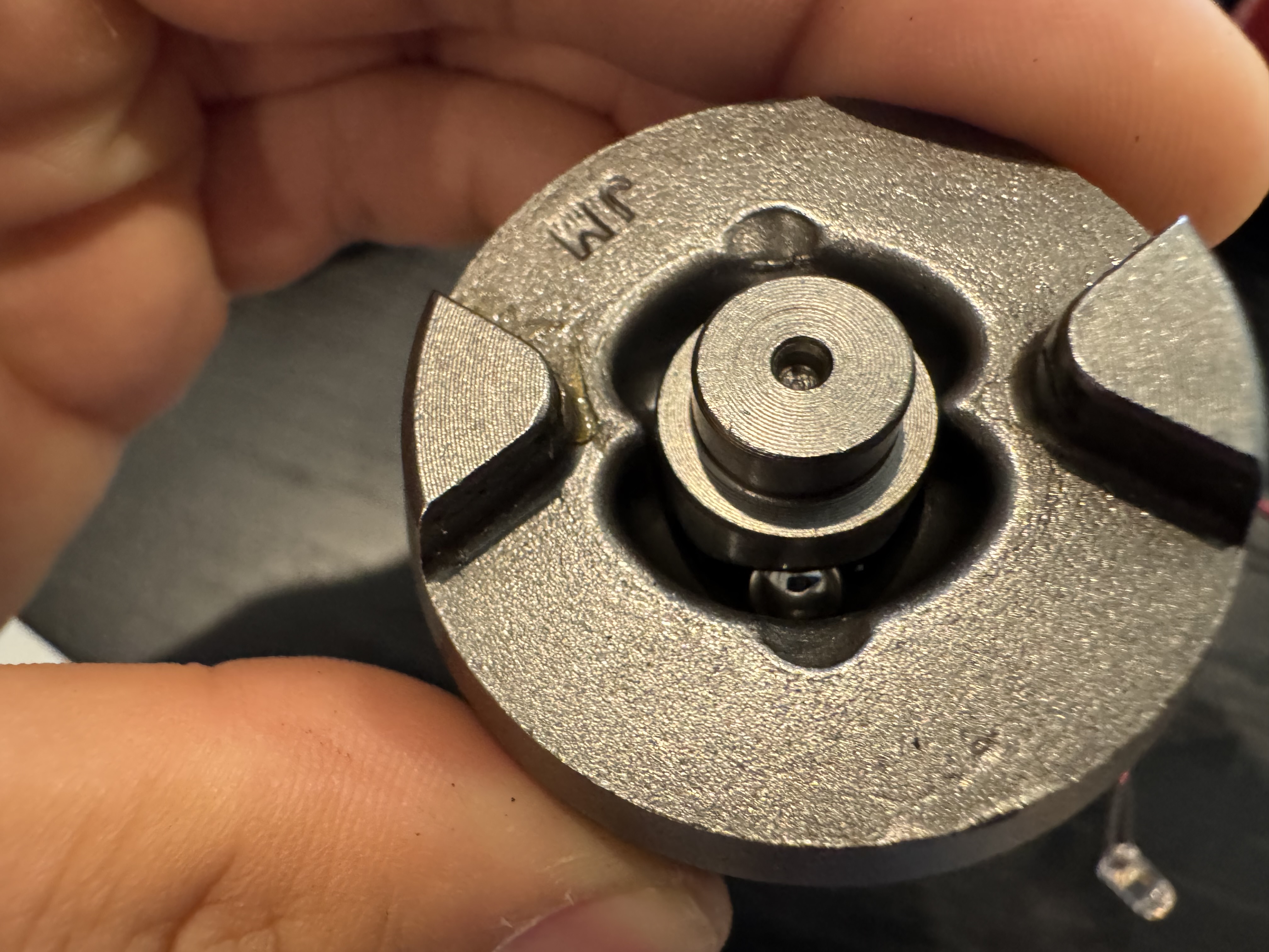
When the trigger is pressed, these little feet movie across on the back, connecting the large copper pads seen. You can see that this connects the board's power. (I'll include a schematic later). This prevents unnecessary power waste coming to this board when it's not in use (definitely useful). Below is my current understanding of the pin's functions.

I will try milling a PCB for it in the Mezzanine later this week. I will be using a Raspberry Pi for the basic control logic.
I went back to MITERS to see if I could verify some basic information with an oscilloscope. I was able to determine that when pressed sufficiently, the red pin goes to ~ 4.7Vrms. When not pressed in sufficiently, it floats around 20 Vrms.
The yellow pin when not connected floats around 20 Vrms and when pressing it goes from around 600 Vrms to 4.7Vrms (around what the red is).
The yellow is connected to the left middle pad on the back which the carriage connects to. Idk why i thought it was ground.
I am measuring the resistor values now. (This was a long segway, so I exlcuded it here). Basically, I realized that the trigger was acting as an artifical analog voltage signal using the carriage moving across slanted pads.
Okay, I think i'm pretty confident about what it is. The pins are isolated until the slider on bottom moves. There appear to be no other copper connections or other traces. As such, I want to make a relay switch that will take in a digital signal of a Raspberry Pi (or some other controller) and then connect these two. I should be able to test this by just connecting them with a wire...
So that was an obvious test lol. It worked. I'll mimic their design just because I'm not sure what the internals look like, so I will be using a relay switch. I think this will do: AQV210E.
I now need to do something to mimic the analog signal that is going into the yellow wire. I think this will be: MCP4725A1T-E/CH.
For now, I think I will be using a floating gnd / connect my rapsi gnd to the lion gnd. It seems a little sketchy to me, but I've probably done similar things before. I'm just worried about it now because It's not something that I would do a lot. Okay, I clamped the motor down and ran a test. It works how I expected. I need to double check the changing of directions, but this looks pretty good right now.
I am going to try working on this more on Saturday. I will be cutting off a lot of the handle probably and maybe making a basic clamping style mount that grabs the from on top and bottom and could be screwed onto a base platform.
(Update: May 24)
I've worked this out a little more. I have not made the mount yet, mostly bc I forgot about it. I was just going to screw into the holes that join the hammer part of the wrench with the part containing the motor. I think that should be sufficient.
That being said, I don't have calipers around me right now, so I'll have to look later.
I've designed a pcb for imitating the trigger, but I'm not 100% about the direction pin, mostly because I think I lost a couple of the components before. Regardless, I have the pcb for it designed as shown below. I have the parts at home, minus the 330 Ohm resistors, so I may order some from digikey. I'm in Philly for the Summer now, so I'll have to get them delivered here. Once I do, I'm hoping to test out the substitute.

So the PCB did come in. Components were soldered on after work on Friday. It's been really hot, so working has been a little bit of a pain and I've just been focused on CAD. It's nice to do some amount of manufacturing. At some point this upcoming week, I will crimp JST wires and have a raspberry pi or maybe a jetson set up to do this. Actually, I think i'll probably take an arduino potentially. It'll eventually go on something heavier, but for testing I think an arduino should be sufficient. I'll probably tkae care of that the 16th. Hopefully there's an update with a video for this at some point.


June 17 2026 Update
Today, I learned how to crimp the JSTs from Glenn, a technician at the company I work for. I haven't interacted with a lot of technicians and I'm continually astounded at the level of precision and attention to detail he has. For example, for crimping, he'll measure out the wire that needs to be stripped with a caliper in order to meet standards (around a .5 mm accuracy requirement).
Also, I hadn't really thought about how i was going to connect the new board to the controller at first, so I just choose JST 2.54 because they're convenient/large. Later, I realized that the ones i'm working with are much smaller.
Anyways, I need to program the raspi or arduino i'll be using. My goal is to hear the impact wrench move tomorrow.